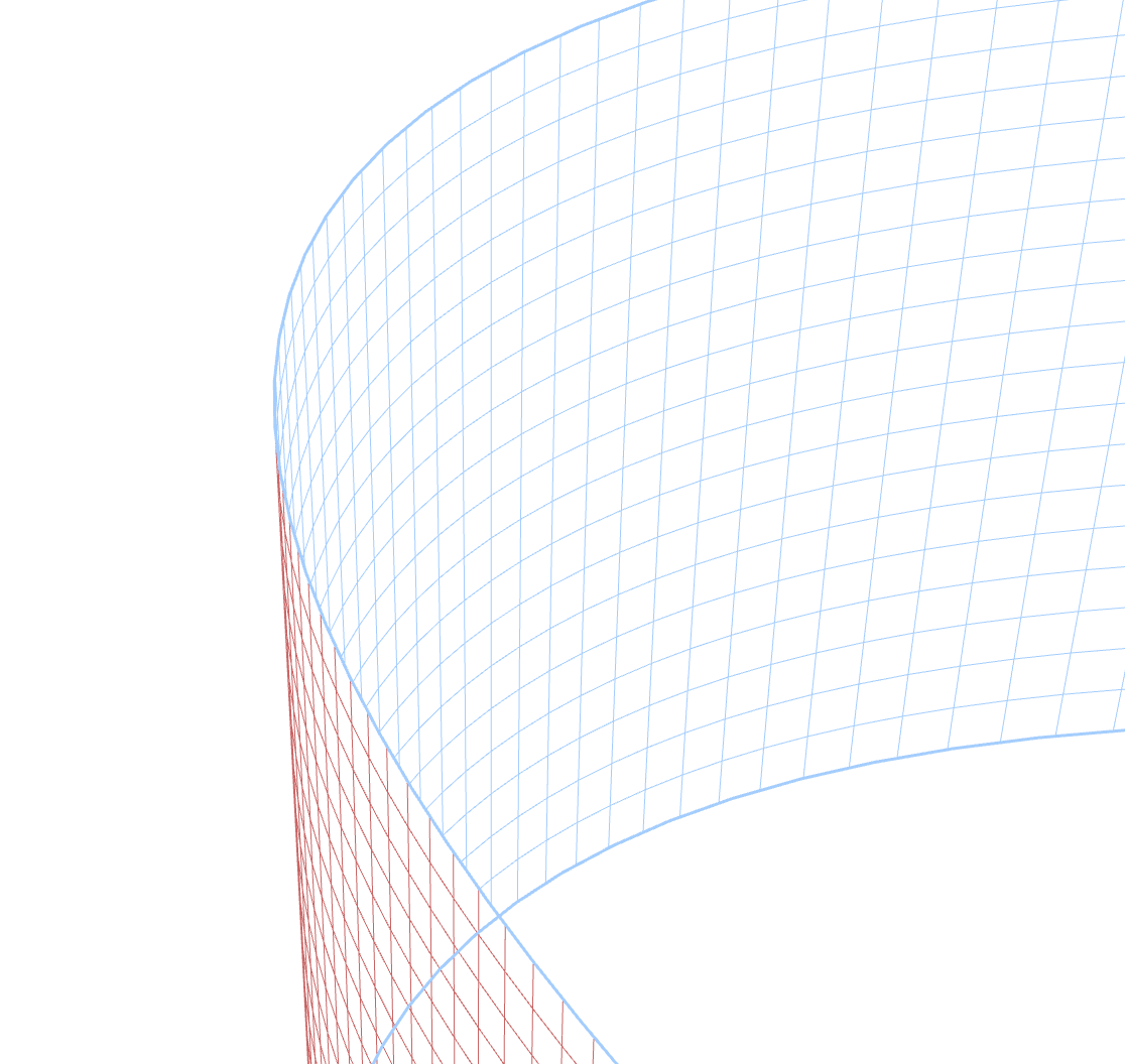
The MESH section of the Properties panel lets you adjust the mesh grid structure of your design in Strokes Maker, making it easier to fine-tune your artwork.
Think of a mesh as a flexible grid that you can reshape to transform your artwork. The Mesh Properties panel gives you control over this grid's structure and behavior. Here you can:
- Add more grid lines (edges) to increase control over specific areas
- Make your mesh behave like a real 3D object with the Hidden Strokes Removal feature
- Control which parts of your artwork are visible when the mesh folds over itself
On this panel, you can quickly add new horizontal or vertical edges to the Mesh grid, switch the object to Hidden Strokes Removal mode, and manage its options.
Learn more about the Mesh grid in this article Mesh.
Adding Edges
Adding edges gives you more control points to reshape your mesh. More edges mean finer control over specific areas of your design.
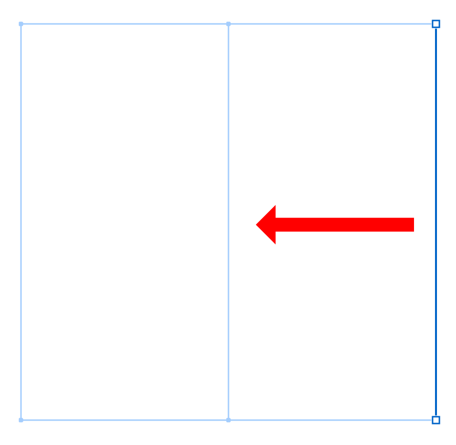
When you select a mesh edge (a grid line), you can easily add new edges adjacent to it. For a vertical edge, you can add edges to the left or right. For a horizontal edge, you can add edges above or below the selected one.
To add an edge:
- Select an edge in your mesh grid
- In the Mesh Properties panel, click one of the edge addition buttons:
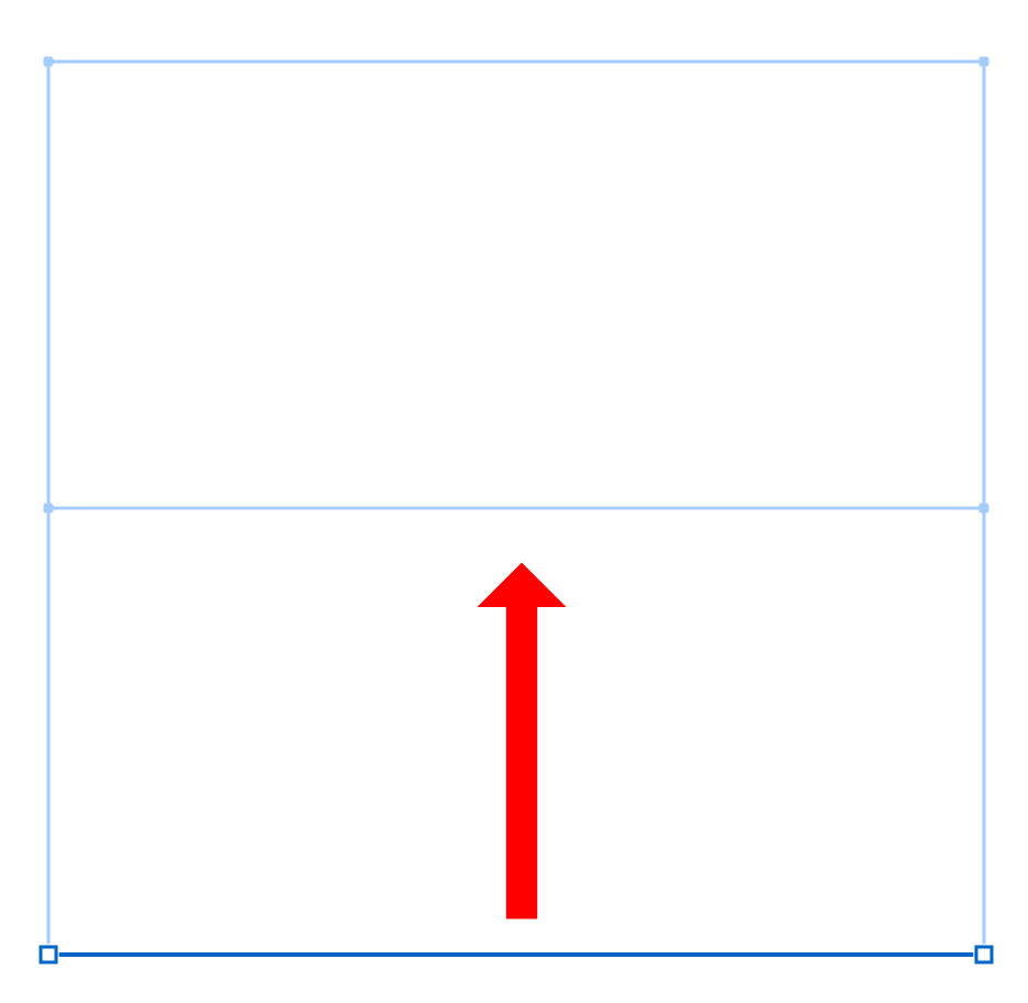
 Add an edge at the top.
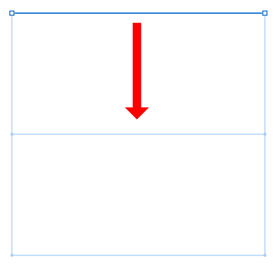
 Add an edge at the bottom.
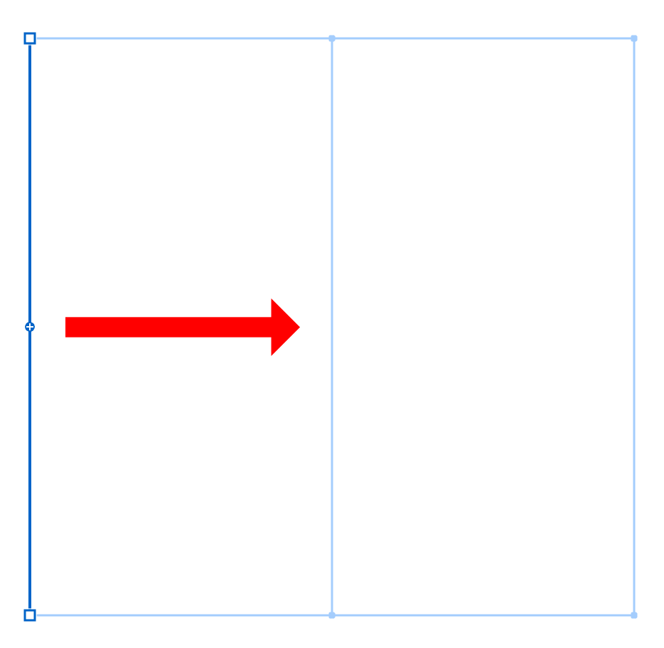
 Add an edge on the right side.
 Add an edge on the left side.
The examples below show how adding edges in different directions affects your mesh:
| Add to the bottom | Add to the top | Add to the right | Add to the left |
|---|---|---|---|
 |
 |
 |
 |
When to Add Edges
Add more edges when you need:
- More precise control over a specific area of your design
- To create complex curves or bends in one part of your mesh
- To add detail to just one section without affecting the entire mesh
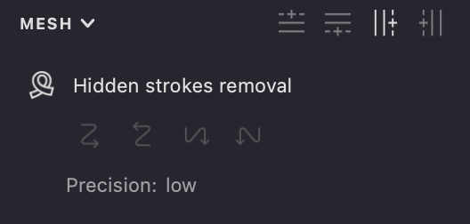
Hidden Strokes Removal
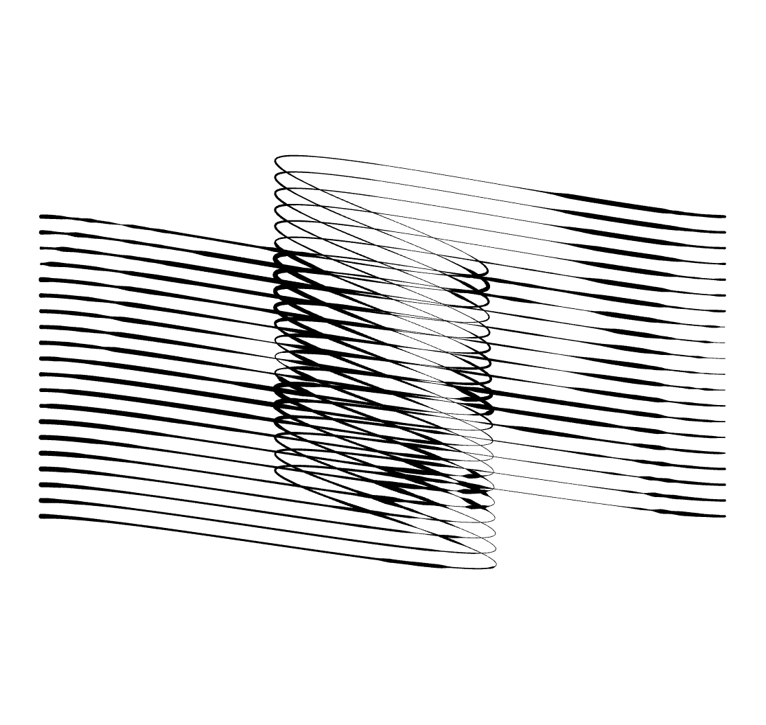
Activating this mode treats the mesh object like an opaque two-sided surface, similar to a sheet of paper. It hides fills that are covered by folds or intersections of the mesh surface.
This feature makes your mesh behave like a real physical object:
- Parts that would be hidden by folds become invisible
- Overlapping sections only show the top layer
- The mesh acts like a solid object rather than a transparent grid
Think of it as folding a piece of paper - when you fold it, you can't see what's on the folded part that's facing away from you.
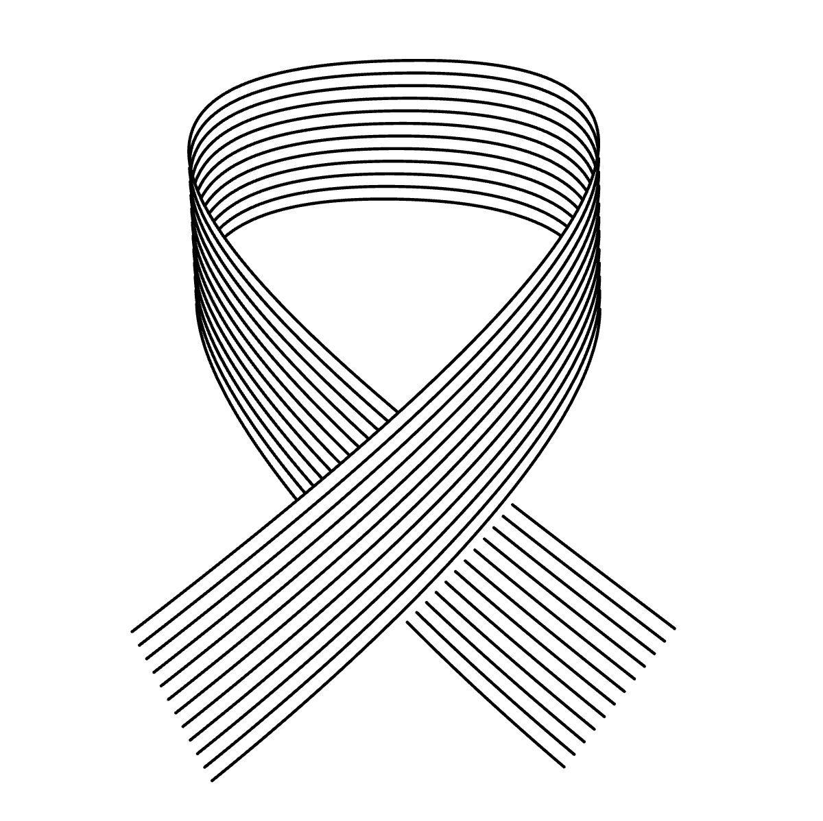
| Hidden Strokes Removal Off | Hidden Strokes Removal On |
|---|---|
 |
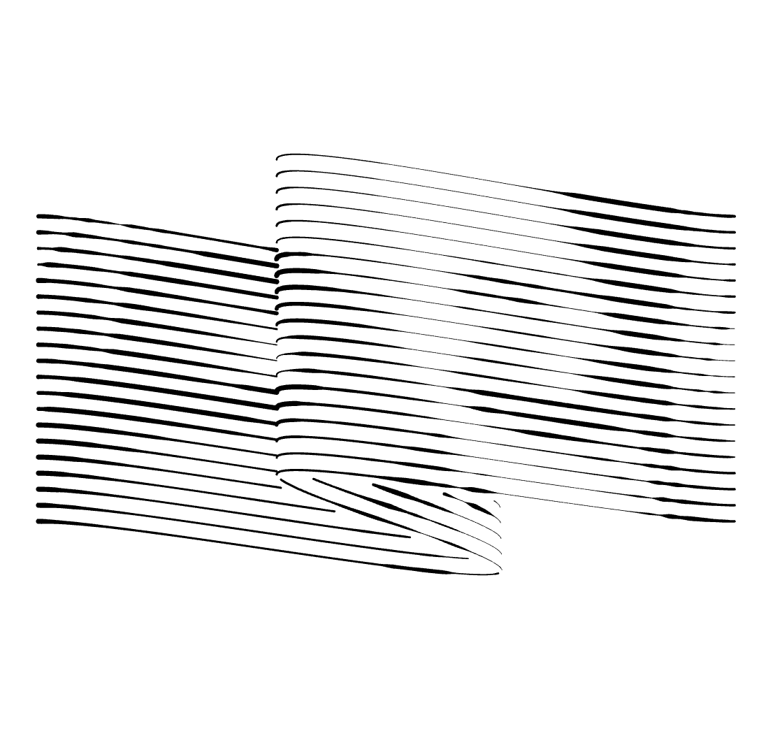 |
In the example above:
- Left: All parts of the mesh are visible, even if they should be hidden by folds
- Right: Parts of the mesh that would be hidden by folds are no longer visible
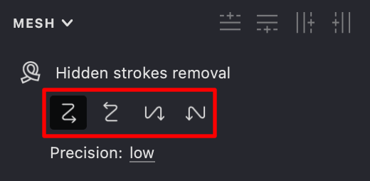
Removal Direction
The lines on the mesh can be drawn in different sequences, and depending on this order, different parts of the mesh surface will be visible.
To set the drawing order, use the four buttons provided.
Direction determines which parts of your mesh are drawn "on top" when there's an overlap:
- The drawing sequence defines which parts of the mesh are considered "in front"
- Changing the direction can dramatically alter which parts of your artwork remain visible
- This is similar to changing your viewing angle of a 3D object
Direction Options
 Top to down, left to right.
 Bottom to up, right to left.
 Left to right, top to bottom.
 Right to left, top to bottom.
These examples show how different direction settings affect which parts of the mesh remain visible:
| Top to down | Bottom to up | Left to right | Right to left |
|---|---|---|---|
 |
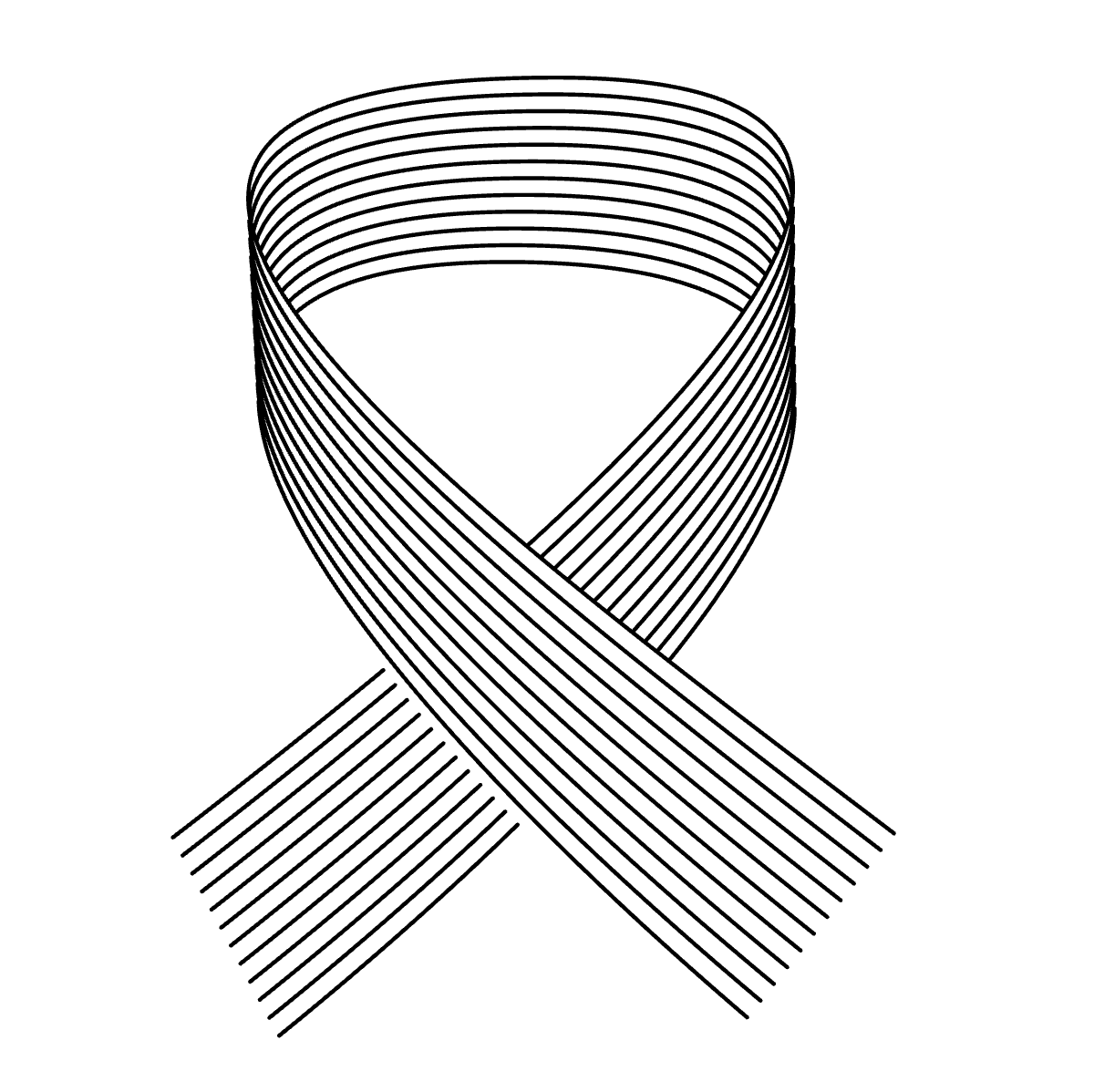 |
 |
 |
Precision Settings
You can adjust the accuracy of removing hidden parts of the fills. In most cases, there's no need to change this setting. However, if your design has tiny details or the mesh has many complex folds, you might need to increase the precision.
Note: Increasing precision can make the fill calculation take longer and use more memory.
Precision controls how accurately Vexy Lines calculates which parts should be hidden:
- Low precision: Faster but may miss small details or create artifacts in complex areas
- Higher precision: More accurate but requires more processing time
- When to increase: If you see unwanted artifacts or incorrect hiding in detailed areas
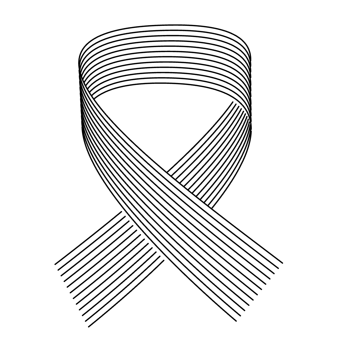
| Low | Normal | High | Greatest |
|---|---|---|---|
 |
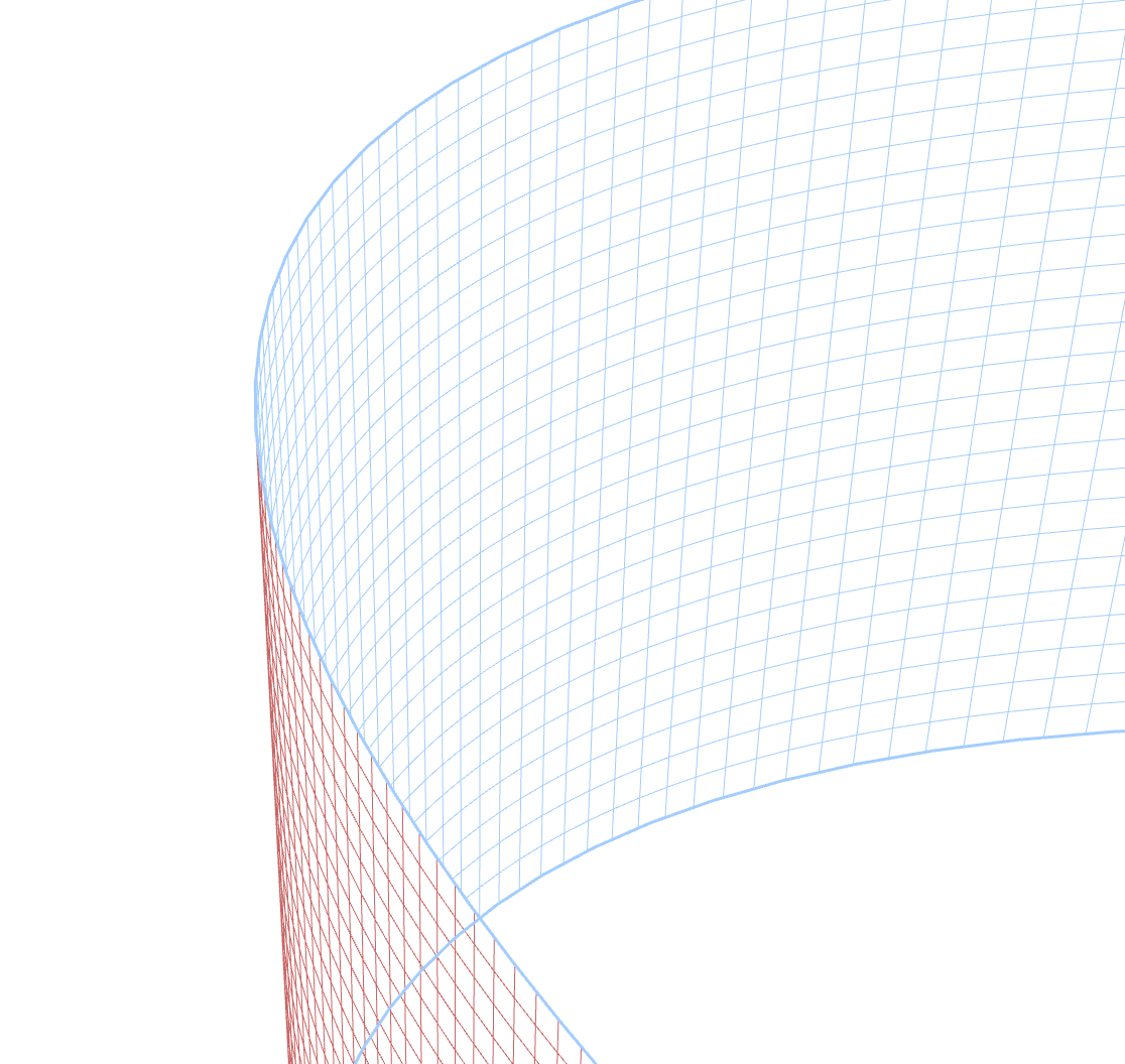 |
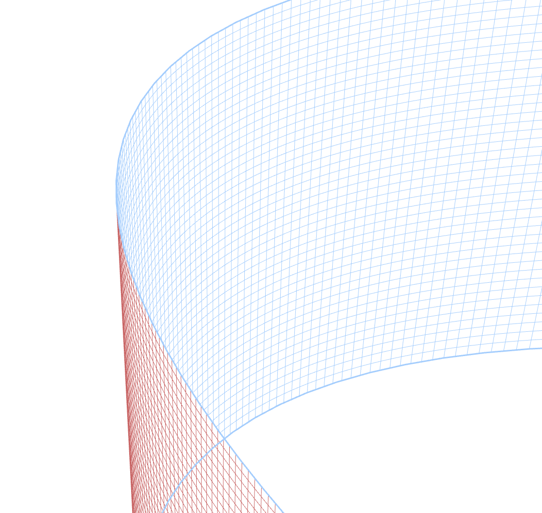 |
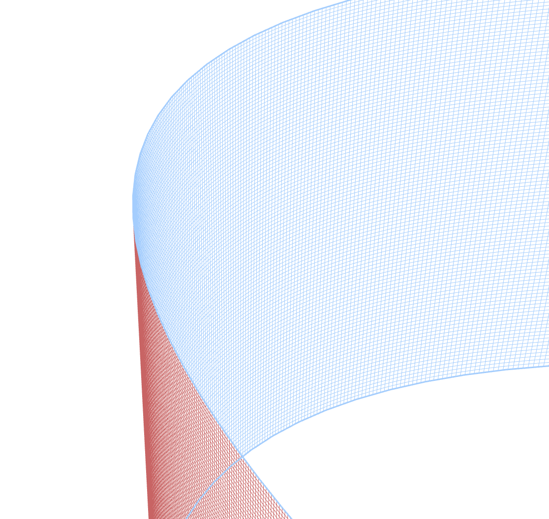 |
Notice how the higher precision settings show cleaner edges and more accurate hiding of overlapped areas.
Common Use Cases
Here are some practical applications for the Mesh Properties panel:
Adding Detail to Specific Areas
Add edges only where you need more control, leaving the rest of the mesh simpler:
- Add edges near curves that need refinement
- Create finer control in areas with important details
- Keep edge count lower in simpler areas for easier editing
Creating Realistic Folded Effects
Use Hidden Strokes Removal to create paper-like folding effects:
- Activate this mode when creating origami-inspired designs
- Experiment with different removal directions to get the desired fold appearance
- Increase precision for crisp fold lines in detailed work
Creating Depth and Perspective
Combine mesh editing with Hidden Strokes Removal to create depth:
- Shape your mesh to create a 3D-like form
- Enable Hidden Strokes Removal to make the depth convincing
- Adjust direction settings to control which parts appear in front
Troubleshooting Common Issues
If your mesh doesn't look right:
- Try different removal directions if the wrong parts are hidden
- Increase precision if you see glitches at intersection points
- Add more edges if you need finer control over a specific area
For more information about editing mesh points and edges, see the Mesh Editing article.